EtherChannel (LACP / PAgP)
Definition
EtherChannel allows you to group multiple physical interfaces into a single logical interface they behave as if they are one interface.
What These Notes Cover
- What EtherChannel is and the problem it solves (Spanning Tree Protocol)
- Methods of configuring both Layer 2 and Layer 3 EtherChannels
Layer 2 vs. Layer 3 EtherChannel
- Layer 2 EtherChannel: A group of switch ports operating as a single interface
- Layer 3 EtherChannel: A group of routed ports operating as a single interface, which you assign an IP address to (because it's Layer 3)
Exam Note
This video covers Topic 2.4 of the official exam topics: configure and verify Layer 2 and Layer 3 EtherChannel using LACP (Link Aggregation Control Protocol)
The Problem EtherChannel Solves
Network Design Terms
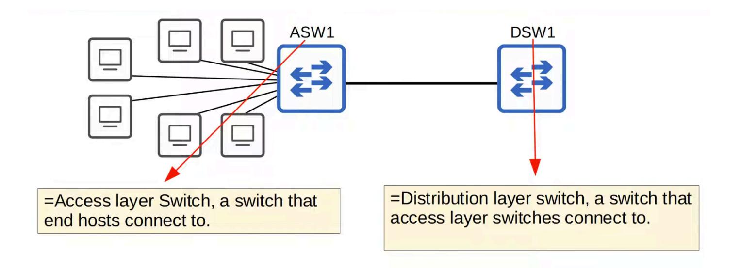
- ASW (Access Switch): A switch that end hosts like PCs and servers connect to
- DSW (Distribution Layer Switch): A switch that access layer switches connect to
Scenario: Link Congestion
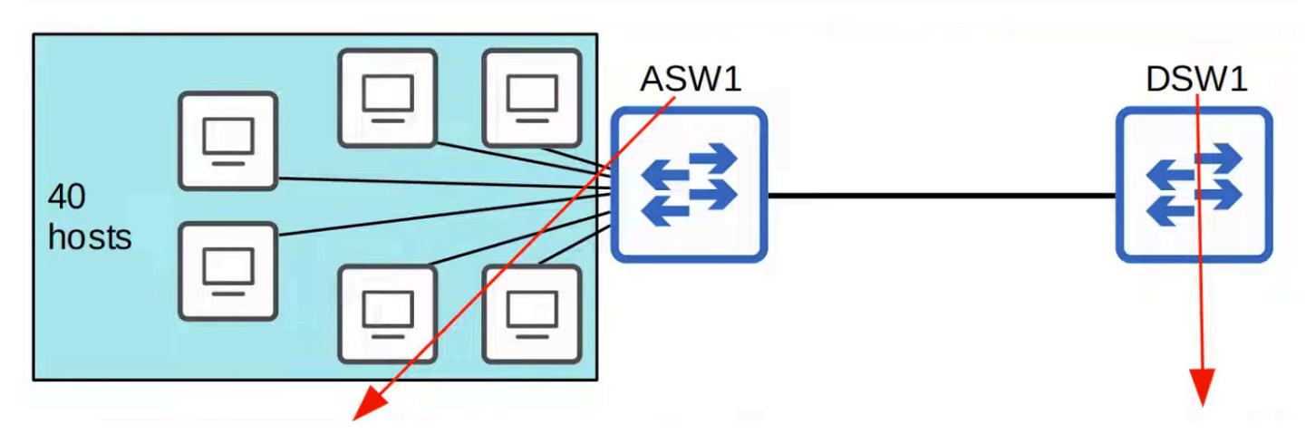
- ASW1 has 40 end hosts connected, all trying to access the Internet
- The single connection to DSW1 becomes congested
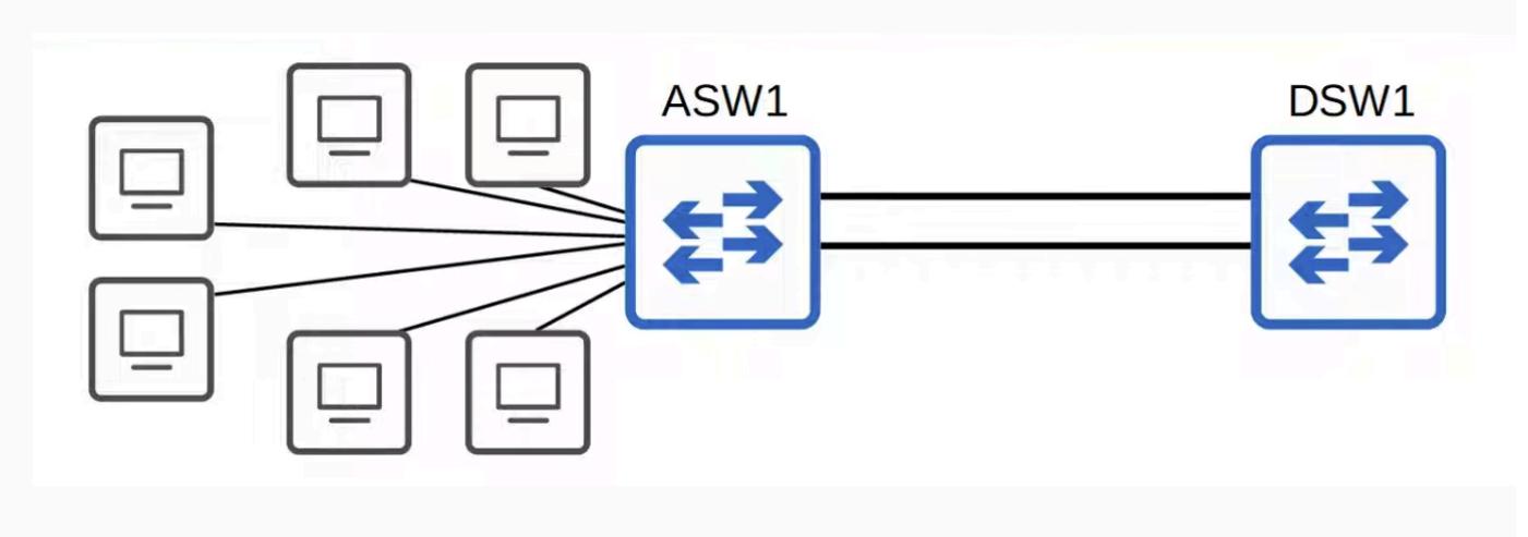
The second connection to DSW1 is also congested
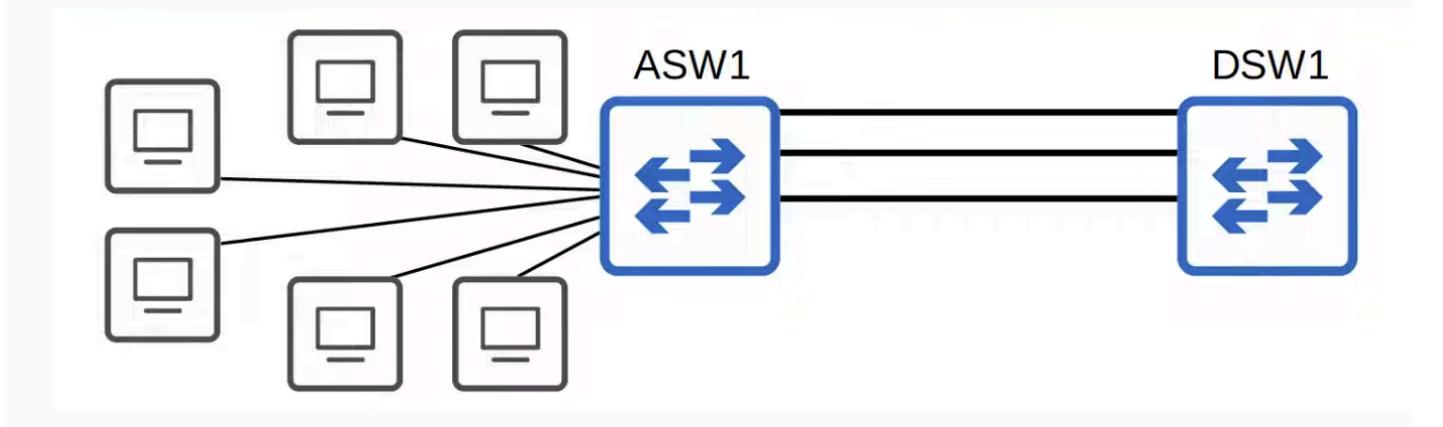
The Third connection to DS1 is also congested
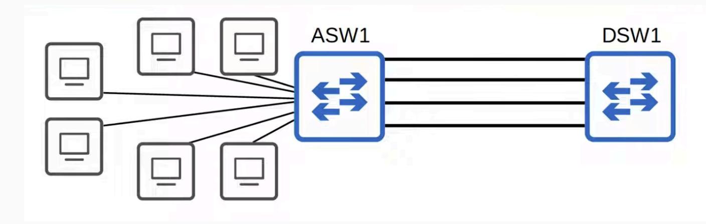
- The network admin adds more links (up to four total) between ASW1 and DSW1
- Congestion doesn't improve why?
Key Concept: Oversubscription
-
Occurs when the total combined bandwidth of interfaces connected to end hosts exceeds the bandwidth of the connection to the distribution switches
-
Example: ASW1 has 40 end hosts connected. Even with three or four links to DSW1, the total bandwidth demand from those hosts is still greater than the uplink capacity
-
Not all hosts send and receive Internet traffic at the same time, so some oversubscription is acceptable
-
However, too much oversubscription will cause congestion and end users will experience problems
-
The Imbalance:
-
Downstream side: 40 end hosts are sharing the interfaces on ASW1 their combined traffic demand is very high
-
Uplink side: Only 4 connections going from ASW1 up to DSW1
-
The total traffic from those 40 end hosts is greater than what those 4 uplink connections can handle
-
That's oversubscription too much demand (from end hosts) vs. not enough capacity (uplink to DSW1)
Simple way to think about it:
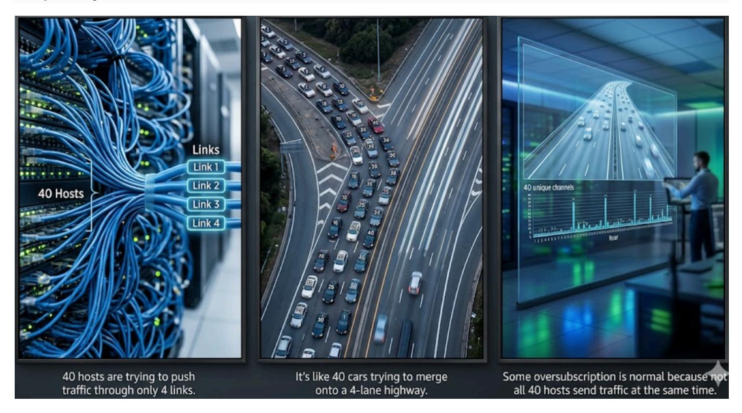
- 40 hosts are trying to push traffic through only 4 links
- It's like 40 cars trying to merge onto a 4-lane highway
- Some oversubscription is normal because not all 40 hosts send traffic at the same time
- But in this case, even 4 links aren't enough the traffic is still congested
The Real Problem: Spanning Tree Protocol
When checking port lights on DSW1:
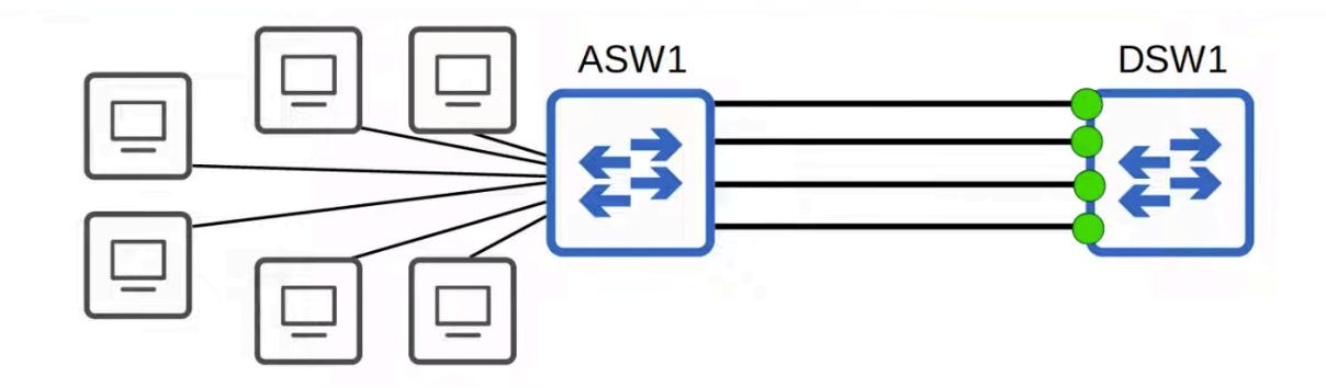
- All links are green (forwarding)
- When checking port lights on ASW1:
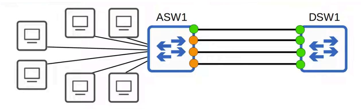
- Only one link is green (forwarding)
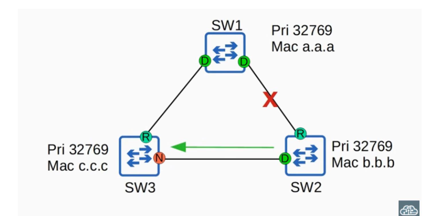
- The other three are orange (blocked by STP)
- STP disables all redundant links except one to prevent Layer 2 loops and broadcast storms
- The inactive links only activate if the active link fails
- Result: Three interfaces sit idle a waste of bandwidth
The Solution: EtherChannel
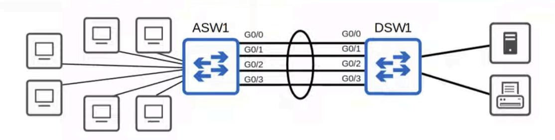
- Groups the four physical interfaces into one logical interface
- Provides both redundancy and increased bandwidth
- STP sees the group as a single link, so it doesn't block any of the member interfaces
How EtherChannel Works
Network Diagram Representation
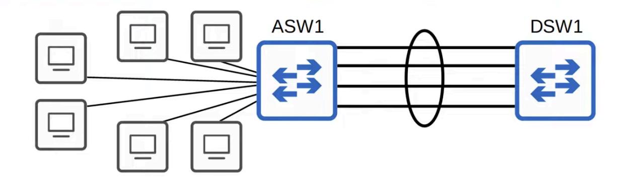
- EtherChannel is represented by drawing a circle around the grouped interfaces
- EtherChannel groups multiple interfaces together to act as a single interface.
STP Behavior
STP treats the EtherChannel group as a single interface
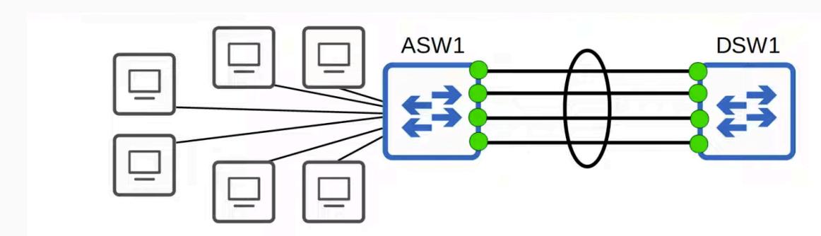
- After grouping, all link lights turn green no ports are blocked
- No Layer 2 loop is formed because the group behaves as one link
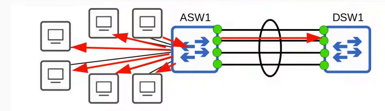
Broadcast Frame Example (Why No Loop Occurs)
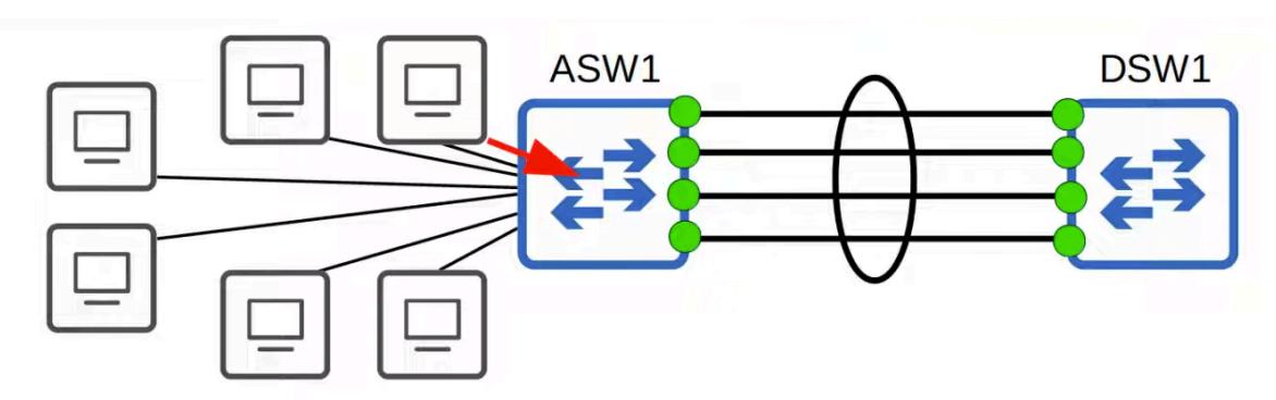
- A PC sends a broadcast frame
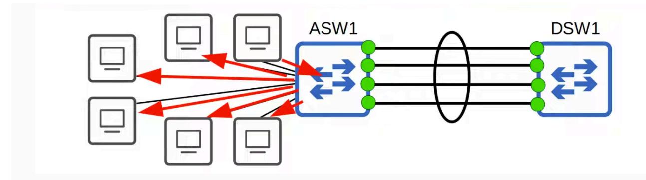
- ASW1 floods it out all interfaces — all local PCs receive a copy
-
- How many copies does DSW1 receive? Only one even though there are four physical links, they behave as a single logical interface
-
- DSW1 floods the broadcast out of all other interfaces, except the one it was received on
-
- DSW1 does not forward the broadcast back to ASW1 no loop
Think of It As
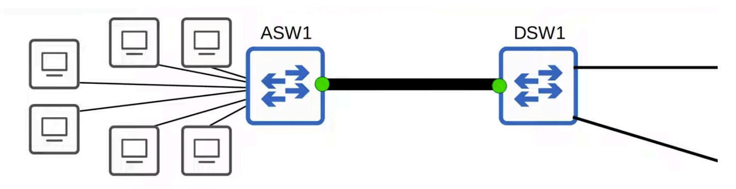
- Instead of four separate 1 Gbps interfaces, it's as if there is a single 4 Gbps virtual interface
- The bandwidth of all physical links is combined into one faster logical link
Physical vs. Logical/Virtual
- VLANs: Multiple PCs on the same switch are physically in the same LAN, but VLANs virtually divide them into separate LANs
- EtherChannel: Four separate physical interfaces form a single virtual interface
- Understanding the difference between physical and logical/virtual characteristics is essential as a network engineer
Other Names for EtherChannel
- Port Channel
- LAG (Link Aggregation Group)
- In Cisco IOS, different terms are used when configuring you'll see all three
EtherChannel Load Balancing
Concept of a "Flow"
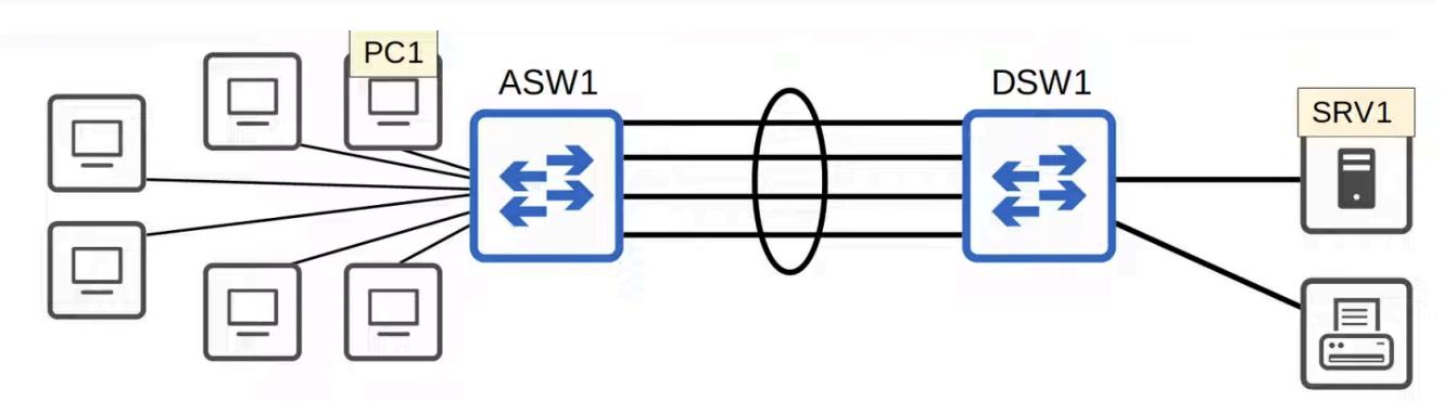
- A flow is a communication session between two nodes in the network (e.g., between PC1 and SRV1).
- Rule: Frames belonging to the same flow are always forwarded over the same physical interface within the EtherChannel.
- Reason: To prevent frames from arriving out of order, which can cause issues for some applications.
How It Works
- PC1 initiates an exchange of data with SRV1
- A frame sent from PC1 to ASW1 Switch
- Assuming it knows the mac address of SRV1 it will forward the frame out of the port channel to DSW1
- However which physical interface will it use?

- An algorithm calculates which physical member interface should carry the traffic
- For example, it might select the third interface in the group
- Any subsequent frames from the same flow (e.g., more communication between PC1 and SRV1) will use that same physical interface
- Key Rule: All frames within a single flow are forwarded over the same physical interface
- Why? If frames in the same flow used different physical interfaces, they could arrive out of order at the destination
- Some applications can handle out-of-order frames
- Others cannot which is why this consistency matters
- Separate Flows, Separate Calculations
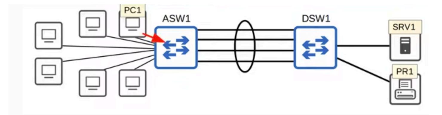
When PC1 initiates a new flow (e.g., connecting to PR1):
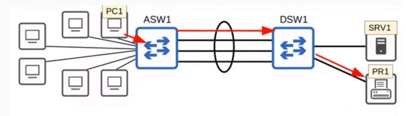
- ASW1 forwards the frame through its virtual port-channel interface.
- It performs a separate calculation to determine which physical interface will be used for this flow.
- For example, it might select a different interface than the one used for the PC1 ↔ SRV1 communication.
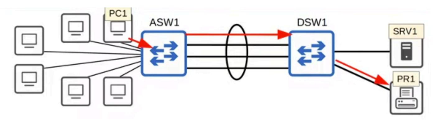
- Just like before, when PC1 sends another frame in that flow, the same member interface of the EtherChannel will be used to forward it.
- How Different Flows are Balanced
- Flow 3 (PC2 ↔ PR1): Algorithm calculates and selects Interface C.
- Summary: This is how EthernetChannel performs load balancing, by using different physical interfaces within the etherchannel for different flows, achieving load balancing across the link.
Load-Balancing Inputs (The Calculation) You can configure what parameters the algorithm uses to decide the physical interface:
MAC Address Based:
- Source MAC: All frames with the same source MAC use the same interface.
- Destination MAC: All frames with the same destination MAC use the same interface.
- Frames from PC1 to SRV1 will always use a certain Interface.
- Frames from PC2 to SRV1 will always use a certain interface which might be the same or different than the one used for traffic from PC1 to SRV1.
- Frames from PC1 to PR1 might use another different interface.
- Source and Destination MAC: Calculation uses both addresses combined.
IP Address Based:
- Source IP: All frames with the same source IP use the same interface.
- Destination IP: All frames with the same destination IP use the same interface.
- Source and Destination IP: Calculation uses both addresses combined.
Layer 4 Port Numbers:
Based on TCP or UDP port numbers (supported on some switch models).
Note:
- The available load-balancing methods depend on the switch model. Some support only MAC, some support MAC and IP, and others support all methods.
- The professor notes that servers/printers usually connect to the Access Layer, but they are shown on DSW1 in this diagram for simplicity.
Configuring and Verifying Load-Balancing
Check Current Load-Balancing Method
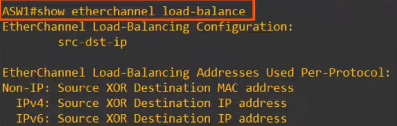
- Use the command show etherchannel load-balance to view the current setting.
- The default method on this model is to load balance based on source and destination IP addresses.
- Example: All traffic from to destination will always use the same physical interface within the etherchannel.
Default Behavior Details

- IP Traffic (IPv4/IPv6): Load-balanced based on source and destination IP addresses.
- Non-IP Traffic: Load-balanced based on source and destination MAC addresses (because no IP addresses are present).
Change Load-Balancing Method
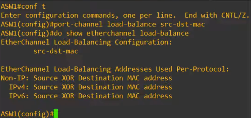
- Enter global configuration mode.
- Use the command port-channel load-balance followed by the method.
On ASW1:
ASW1# show etherchannel load-balance
(Displays default: src-dst ip)
ASW1# configure terminal ASW1(config)# port-channel load-balance src-dst-mac ASW1(config)# end ASW1# show etherchannel load-balance
(Verifies change to src-dst mac)
Available Methods
- Load balance based on MAC or IP addresses.
- Load balance based on source, destination, or both source and destination addresses.
- Examples:
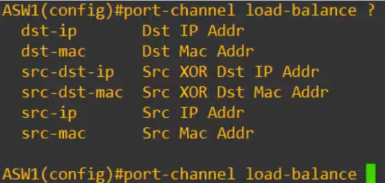
- dst-ip All frames with the same destination IP address use the same physical interface
- dst-mac All frames with the same destination MAC address use the same physical interface
- src-dst-ip Calculation uses both source and destination IP addresses combined
- src-dst-mac Calculation uses both source and destination MAC addresses combined
- src-ip All frames with the same source IP address use the same physical interface
- src-mac All frames with the same source MAC address use the same physical interface
Cisco IOS Quirk (Note)

- To configure: Use keyword port-channel.
- To verify: Use keyword etherchannel.
- The professor notes this terminology inconsistency is frustrating.
Summary of Commands
- show etherchannel load-balance: To check the method.
Methods of Configuration
There are three methods to configure an EtherChannel.
PAgP (Port Aggregation Protocol)
- Definition: Cisco proprietary protocol (can only be used between Cisco switches).
- Function: Dynamically negotiates the creation and maintenance of the EtherChannel.
- Comparison: Functions similarly to DTP (Dynamic Trunking Protocol) which negotiates trunk formation.
- Behavior: Switches send frames to neighbors to agree on forming an EtherChannel.
LACP (Link Aggregation Control Protocol)
- Definition: Industry standard protocol (IEEE 802.3ad).
- Vendor Support: Works with switches from different vendors (e.g., Cisco, Juniper).
- Function: Dynamically negotiates the creation and maintenance of the EtherChannel.
- Status: Preferred method for configuring EtherChannels.
- Exam Note: The official exam topics list specifically mentions LACP, though familiarity with all methods is recommended.
Static EtherChannel
- Definition: No negotiation protocol is used.
- Configuration: Interfaces are statically configured to form an EtherChannel.
- Drawback: Usually avoided because the switch cannot dynamically maintain the group (e.g., it won't automatically remove an interface if a problem occurs).
EtherChannel Limits
- Standard Limit: Up to 8 interfaces can be active in a single EtherChannel.
- LACP Exception: LACP allows up to 16 interfaces.
- 8 active interfaces.
- 8 standby interfaces (ready to take over if an active interface fails).
Configuration of EtherChannel Methods
General Configuration Approach
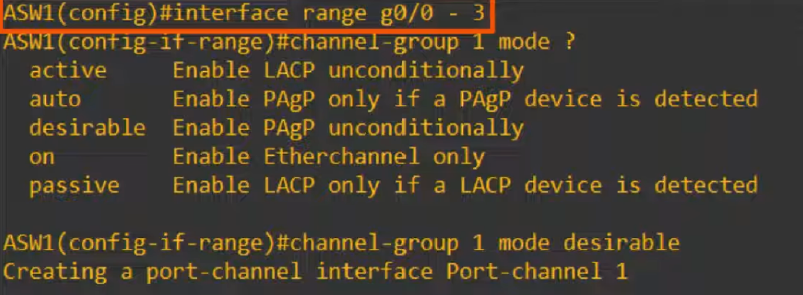
- The configuration for each method (PAgP, LACP, Static) is almost identical, just with different keywords.
- It is best practice to use the interface range command to configure all member interfaces at once. This ensures that the configurations on each member interface match, which is a requirement for forming an EtherChannel.
PAgP Configuration
On ASW1:
ASW1# configure terminal
ASW1(config)# interface range GigabitEthernet 0/0 - 3
ASW1(config-if-range)# channel-group 1 mode desirable
- The channel-group command creates the EtherChannel.
- 1 is the number identifying the virtual interface.
- mode determines the negotiation behavior.
PAgP Modes
- Desirable: Actively tries to form an EtherChannel.
- Auto: Passive; only forms an EtherChannel if the other side is set to desirable.
- Summary:
- Auto + Auto = No EtherChannel.
- Desirable + Auto = EtherChannel.
- Desirable + Desirable = EtherChannel.
Verification
- The virtual interface is created as Port-Channel 1.
- channel-group number must match between interfaces on the local switch, but does not need to match the neighbor switch (e.g., ASW1 group 1 can connect to DSW1 group 2).
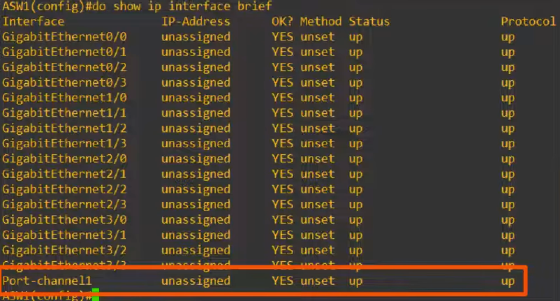
ASW1# show ip interface brief
LACP Configuration
On ASW1:
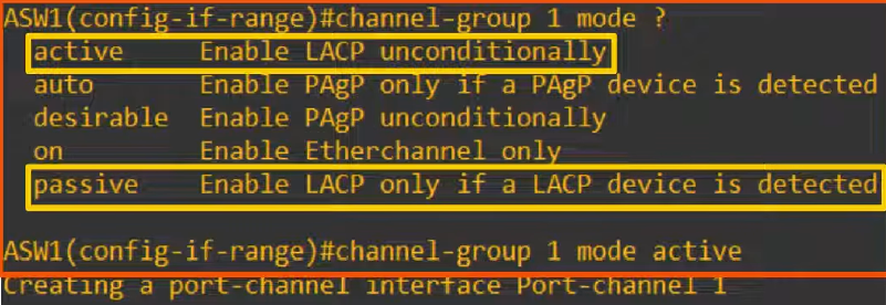
ASW1# configure terminal
ASW1(config)# interface range GigabitEthernet 0/0 - 3
ASW1(config-if-range)# channel-group 1 mode active
LACP Modes
- Active: Actively tries to form an EtherChannel (equivalent to PAgP's desirable).
- Passive: Passive; only forms an EtherChannel if the other side is set to active (equivalent to PAgP's auto).
Summary:
Passive + Passive = No EtherChannel.
Active + Passive = EtherChannel.
Active + Active = EtherChannel.
Note: Even if both sides are configured in passive mode, the virtual port-channel interface will still be created on each switch. However, it won't actually be functioning as an EtherChannel unless at least one side is in active mode.
Channel-Group Number
- The channel-group number must match between member interfaces on the local switch.
- It does not need to match the number on the neighbor switch.
Static EtherChannel Configuration
On ASW1:
ASW1# configure terminal
ASW1(config)# interface range GigabitEthernet 0/0 - 3
ASW1(config-if-range)# channel-group 1 mode on
Static Mode
- Mode on**:** Manually tells the interfaces to form an EtherChannel without any negotiation protocol.
- A port-channel interface is created automatically, just like with PAgP and LACP.
Compatibility Rules
- on + on = EtherChannel formed.
- on + desirable = No EtherChannel.
- on + active = No EtherChannel.
Note: You cannot mix static mode (on) with any negotiated mode (desirable, auto, active, passive). Both sides must use on for static EtherChannel to work.
The channel-protocol Command and Protocol Mismatch
Manual Protocol Selection
- You can manually set the negotiation protocol using channel-protocol.
- Note: This command is generally unnecessary because the mode automatically determines the protocol (e.g., active implies LACP, desirable implies PAgP).
Protocol Mismatch Verification

If you manually set channel-protocol lacp, you cannot use PAgP modes.

Attempting channel-group 1 mode desirable will be rejected because desirable is PAgP, but the interface is forced to LACP.

Attempting channel-group 1 mode on is also rejected in this context.

channel-group 1 mode active is accepted because active is an LACP mode.
Configuring the Port-Channel Interface
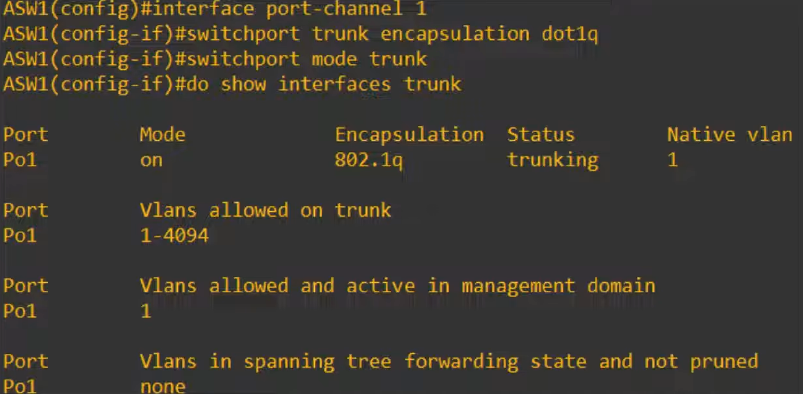
- After the physical interfaces are grouped, configure the virtual Port-Channel interface.
- This configuration applies to the entire bundle.
On ASW1:
ASW1# configure terminal
ASW1(config)# interface Port-channel 1
ASW1(config-if)# switchport mode trunk
On DSW1:
DSW1# configure terminal
DSW1(config)# interface Port-channel 1

Verification
ASW1# show interfaces trunk
(Output shows Po1 as the trunk interface, not the individual physical ports).
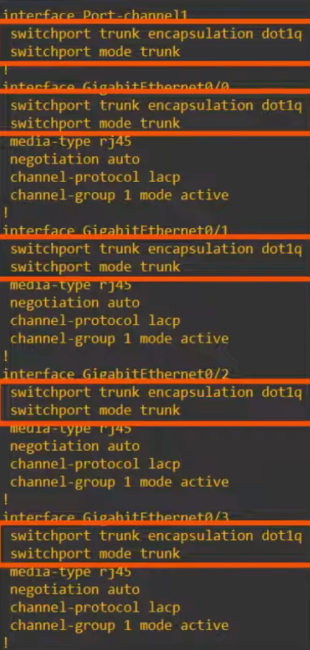
ASW1# show running-config
(Note: Trunk configuration on Port-channel 1 is automatically applied to the member physical interfaces).
EtherChannel Member Interface Requirements
Configuration Matching
- Member interfaces, the physical interfaces in the EtherChannel, must have matching configurations.
- If an individual interface's configurations do not match the others, it will be excluded from the EtherChannel.
What Must Match:
- Same duplex setting (e.g., full-duplex)
- Same speed (e.g., 1 Gbps)
- Same switchport mode (both access or both trunk)
- If trunk: same allowed VLANs and same native VLAN
Note: Using the interface range command to configure all member interfaces at once ensures matching configurations and prevents an interface from being excluded.
Verifying EtherChannel Status
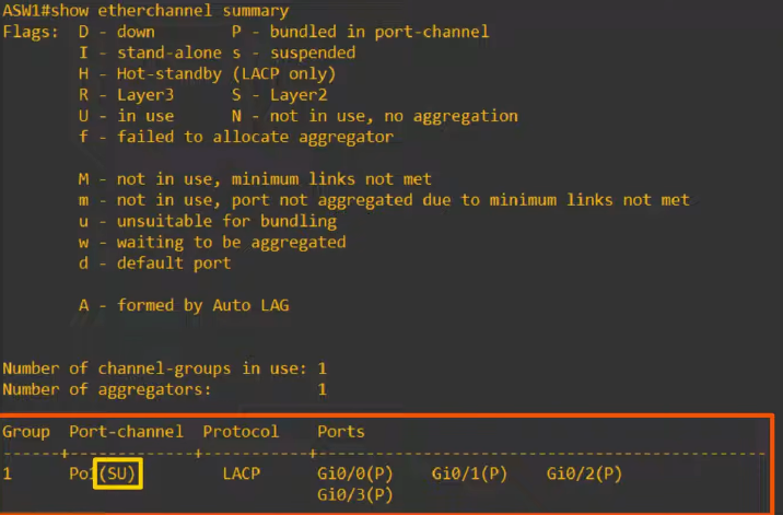
Primary Verification Command
Use show etherchannel summary to view the status of all EtherChannels on the switch.
On ASW1:
ASW1# show etherchannel summary
Flag Meanings (Legend)
- S (Upper-case S): Layer 2 EtherChannel. S stands for Switchport.
- U (Upper-case U): In Use. The EtherChannel is active and being used.
- P**:** Properly bundled in the port-channel. This is the ideal state for member interfaces.
- D**:** Down. The interface or EtherChannel is down (e.g., shutdown).
- s (Lower-case s): Suspended. The interface is excluded due to a configuration mismatch (e.g., wrong switchport mode). The EtherChannel continues to operate with the remaining matching interfaces.
Ideal Status for Layer 2 EtherChannel:
- Next to the Port-Channel interface: S and U.
- Next to the member physical interfaces: P.
Scenario: Mismatch Causes Suspension
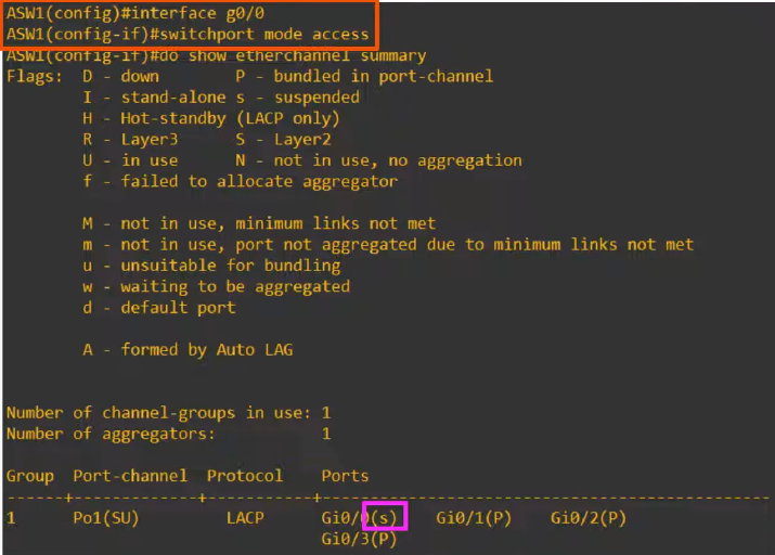
- If a member interface is configured differently (e.g., changed to access mode while others are trunks), it will be suspended.
- Example: GigabitEthernet0/0 shows s, while GigabitEthernet0/1, G0/2, and G0/3 show P. The EtherChannel operates with three interfaces.
Scenario: Shutdown Interface

If the port-channel interface is shut down, it and all its members will show the D flag.
ASW1# configure terminal ASW1(config)# interface Port-channel 1 ASW1(config-if)# shutdown ASW1(config-if)# no shutdown
Additional Verification: show etherchannel port-channel
ASW1# show etherchannel port-channel
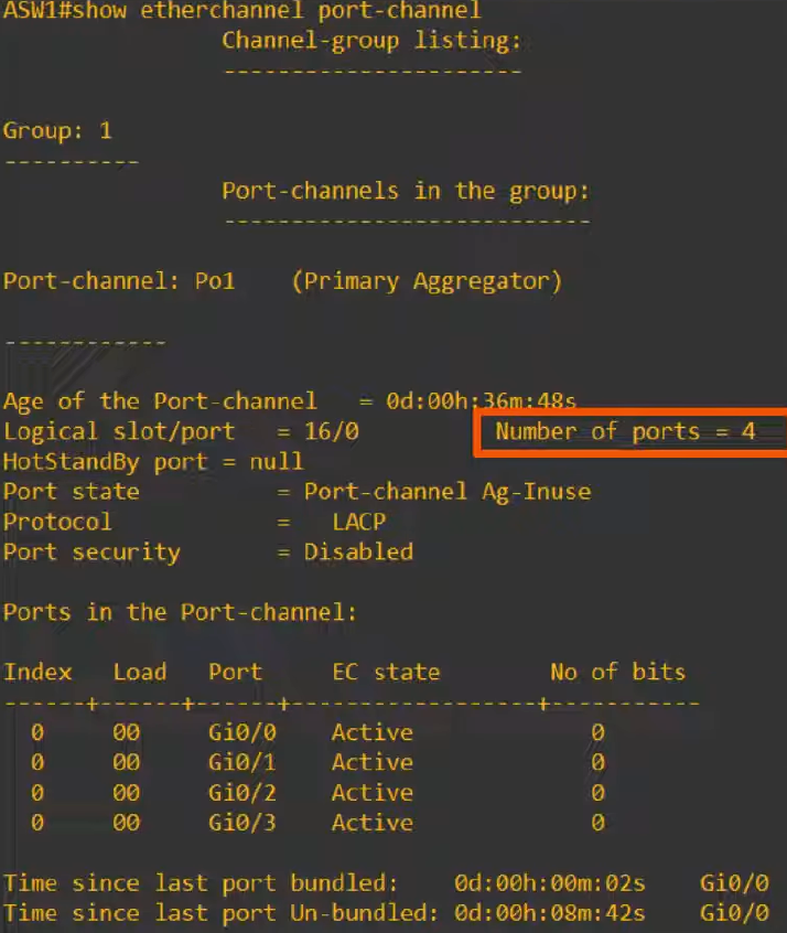
Output Details: Displays information such as the number of ports in the bundle, the protocol in use, etc.
- Key Difference: Unlike show etherchannel summary, this command displays the Channel-Group Mode (e.g., active).
- Note: show etherchannel summary is the most commonly used command, but this command is a good alternative for specific details.
Spanning Tree Protocol Behavior
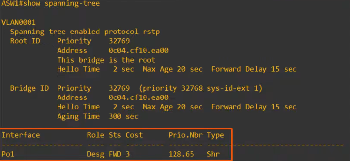
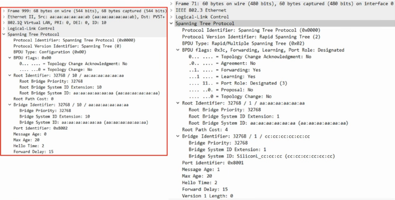
- When verifying STP with EtherChannel configured, only the Port-Channel interface appears in the output (e.g., show spanning-tree).
- The individual physical interfaces are hidden from STP.
- Result: STP treats the group as a single logical interface. Instead of blocking redundant links, all links in the bundle forward traffic, fully utilizing the bandwidth with no risk of Layer 2 loops.
Layer 3 EtherChannel Configuration
Modern Network Design Context
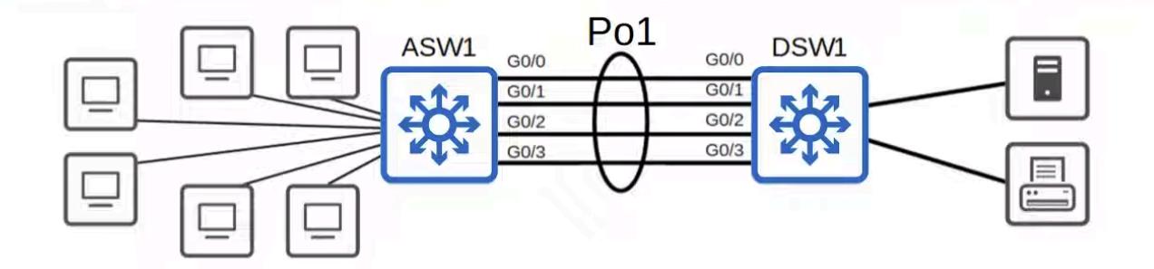
- Replaced ASW1 and DSW1 with multilayer switches.
- Layer 3 connections between switches are often preferred.
- Benefit: Spanning Tree Protocol (STP) is not required because routed ports do not forward Layer 2 broadcasts, preventing loops entirely.
Why EtherChannel alone isn't enough for complex topologies
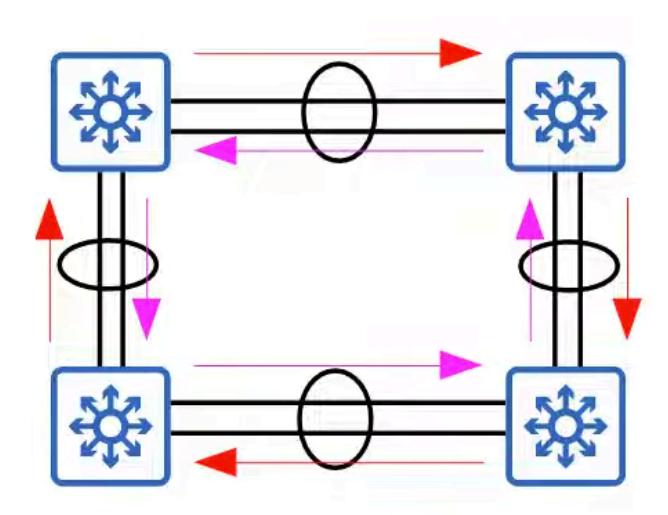
In a mesh of multiple switches, even with EtherChannel, STP still has to block one of the portchannel interfaces to prevent loops.
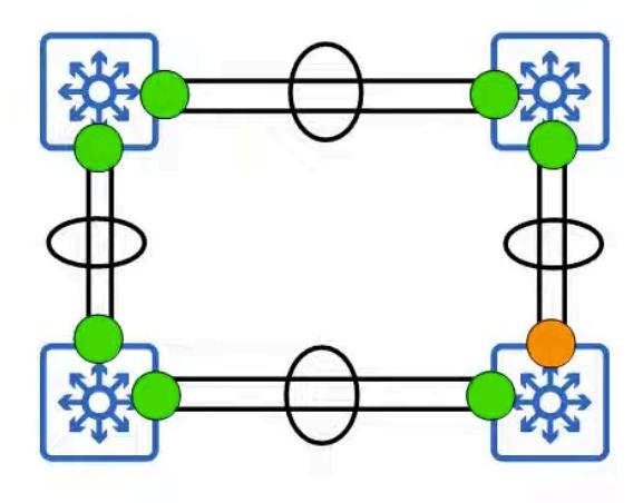
Using Layer 3 routed ports allows all paths to be active and forwarding.
Step 1: Configure Member Interfaces as Routed Ports

- Convert physical interfaces to Layer 3 routed ports using the no switchport command.
- Bundle them into the EtherChannel.
On ASW1:
ASW1# configure terminal
ASW1(config)# interface range GigabitEthernet 0/0 - 3
ASW1(config-if-range)# no switchport
ASW1(config-if-range)# channel-group 1 mode active
Note: The no switchport command is applied to the Port-Channel interface automatically when configured on the physical members first.
Step 2: Configure the Port-Channel Interface
Assign an IP address to the logical interface.
On ASW1:

ASW1(config)# interface Port-channel 1 ASW1(config-if)# ip address 10.0.0.1 255.255.255.0
Verification
ASW1# show running-config
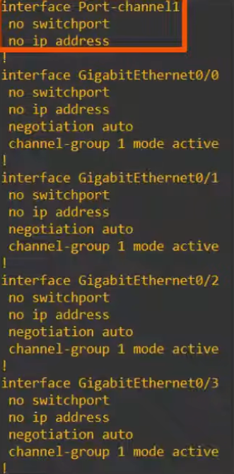
(Confirms Port-Channel 1 has no switchport and the IP address).
ASW1# show etherchannel summary
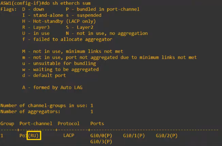
- Status Flag: Look for R next to the port-channel interface.
- R stands for Routed port, indicating a Layer 3 EtherChannel (replaces S for Switchport).
ASW1# show ip interface brief
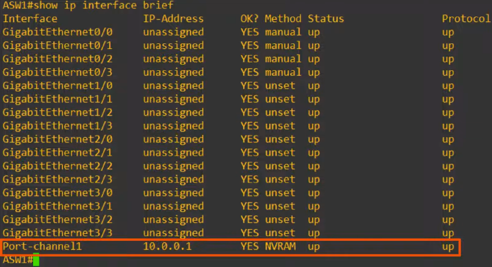
(Displays the IP address assigned to Port-channel 1*).*
Conclusion
- ASW1 and DSW1 now operate as routers connected at Layer 3.
- STP is not running on this connection.
- Traffic is load-balanced over the member interfaces.
Command Review
Load-Balancing Configuration
- port-channel load-balance [mode] Configures the load-balancing method.
- Depending on the switch model, this can be based on MAC addresses, IP addresses, or Layer 4 port numbers.
- Can be set to use source, destination, or both.
- show etherchannel load-balance Views the current load-balancing configuration.
EtherChannel Configuration
channel-group [number] mode [mode] — Configures an interface to be part of an EtherChannel.
Modes available: desirable, auto, active, passive, or on.
Verification Commands
- show etherchannel summary The most useful show command. Displays a summary of all EtherChannels on the switch and their status flags.
- show etherchannel port-channel Displays more detailed information about the port-channel interfaces on the switch.
Exam Note
Understanding the basic purpose of EtherChannel, how to set them up, and how to verify their status is sufficient for the CCNA.
Reinforce Your Knowledge
$ ./quiz — EtherChannel (LACP / PAgP)
question 1/50score: 0/50Q1.What does EtherChannel allow you to do?
0/50 answered
$ ./flashcards — Study Deck
card 1/18seen: 0/18# front · click or press space to flipWhat does LAG (EtherChannel) stand for?# back · answerLink Aggregation Groupagain:0good:0easy:0